
Explosion Proof Field Indicator
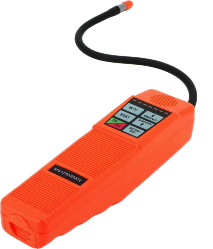
Portable SF6 Leak Detector
$1,633.00Available

Your Global Authority In Hazardous Areas
Your cart is empty.
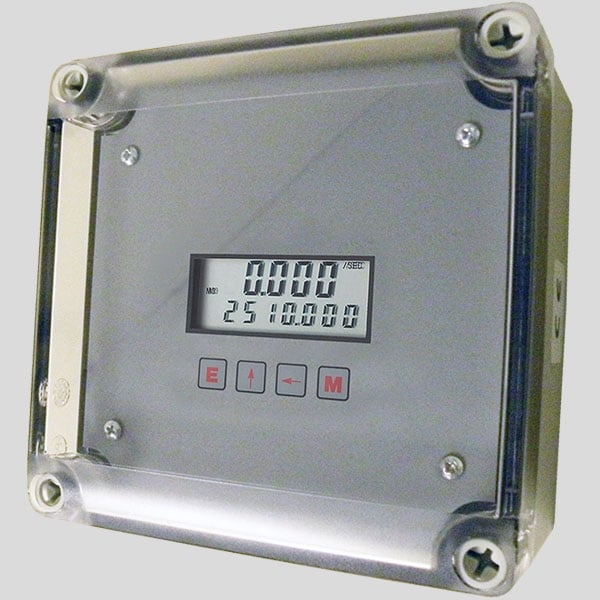
The KEP BATRT-M Intrinsically Safe Field Indicator is approved for use in Class I Division I hazardous sites. It has a rate display of five digits and a total display of eight digits. It is a battery or loop-powered indication that accepts magnetic pickup, DC pulse, and switch closure inputs from the pulse generating flow meters. The most often used output choice is 4-20mA, while another is Modbus RTU communications.
| Hazardous Area Rating | Class 1 Division 1 |
The Intrinsically Safe Field Indicator KEP BATRT-M is a battery- or loop-powered flow totalizer and ratemeter that is approved for use in Class I Division I hazardous areas. The KEP BAT R/T-M, with five rate digits and eight total digits, is a battery- or loop-powered indicator that accepts magnetic pickup, DC pulse, and switch closure inputs from the pulse generating flow meters. The device may be provided with a 4-20mA output as an option. When this output is used, the BATRT-M powers it via the 4-20mA loop.
The BATRT-Millennium is equipped with a Modbus option; the Modbus RTU protocol is used. This protocol specifies a message format that hosts and clients will recognize and utilize while communicating over the Modbus network.
RTU Mode
BATRT-Millennium Communication Setup Menu
The optional linearization of this model provides the 20 point linearization table. A common output is the 4-20mA this makes the unit into 2 wire loop-powered device where 4-20mA is proportional to flow rate. Another option available for this unit is the RS45 Modbus RTU communication options. This is a widely used automation protocol, and the signal may be carried up to 4000 feet.
| DISPLAY: | |
| Rate Display: (selectable decimal) | |
| 5 Digits (99999), 0.35” High, Display updates once per second with battery power, 8X per second with DC or Loop power Rate Descriptors: | |
| /SEC, /MIN, /HR | |
| /MIN, /HR, /DAY with “D” option | |
| Min. Input Frequency: 0.01 Hz to 10 Hz (selectable delay of 0.1 to 99.9 seconds) Selectable Rate Display Damping | |
| Totalizer Display: (selectable decimal) | |
| 8 Digits (99999999), 0.2” High Totalizer Descriptors: | |
| GAL, LIT, FT3, M3, “blank” | |
| GAL, BBL, MCF, M3, “blank” with “D” option | |
| Warning Displays: Low battery warning | |
| PULSE OUTPUT: | |
| The pulse output advances with the least significant digit of the totalizer or decimal multiples there of (see Pulse scale divider). | |
| Type: Isolated photomos relay | |
| Max. voltage (off state): 30 VDC | |
| Current (on state): 100mA | |
| Pulse Duration: Selectable 0.5, 0.25, 0.125, 0.0625 seconds | |
| Pulse Scale divider (Pulscale): User selectable, ÷1, ÷10, ÷100 or OFF | |
| NOTE: Select OFF for max. battery life. | |
| ACCURACY: | |
| 0.01% Reading, ±1 count | |
| Temperature Drift: 50 ppm/°C Worst Case | |
| SAFETY LISTINGS (Mounting Styles 3, 3NE, 3SS): | |
| CSA File 091109 (cert. 1120094) | |
| UL/C-UL File E225832 | |
| CLASS 1, DIV 1, GROUPS B, C, D | |
| Additional "enclosure only" approvals available for ATEX and IEC | |
| ENVIRONMENTAL: | |
| OPERATING TEMPERATURE: -4°F (-20°C) to + 158°F (70°C) | |
| Extended Temp: -22°F (-30°C) to + 158°F (70°C) | |
| HUMIDITY: 0 - 90% Noncondensing | |
| MOUNTING STYLES: | |
| 0- Circuit Board- OEM option (consult factory) | |
| 1- Panel Mount - NEMA 4X Front | |
| 2- Wall Mount - NEMA 4X Enclosure (keypad mounted behind clear cover) | |
| 3- Explosion Proof - Class I, Division I, Groups B, C & D | |
| Class II, Division I, Groups E, F & G | |
| 3ΝΕ- Explosion Proof - White, Includes Third Conduit Entry | |
| Class I, Division I, Groups B, C & D | |
| Class II, Division I, Groups E, F & G | |
| 3SS- Explosion Proof - Stainless Steel | |
| Class I, Division I, Groups B, C & D | |
| Class II, Division I, Groups E, F & G | |
| 5- Wall Mount - NEMA 4X Enclosure (keypad mounted on cover) | |
| 6- Double Ended Explosion Proof - Class I, Division I, Groups B, C & D | |
| Class II, Division I, Groups E, F & G (contact factory for details) | |
| NOTE: Meter mounting kits available for styles 2, 3, 5 and 6 Consult Factory | |
| INPUTS: | |
| MAGNETIC PICKUP INPUT | |
| Frequency Range: 0 to 3500 Hz | |
| Trigger Sensitivity: 10 mV p-p | |
| Over Voltage Protected: ± 30 VDC | |
| OPTO-ISOLATED DC PULSE INPUT | |
| High (logic 1): 4-30 VDC | |
| Low (logic 0): Less Than 1 VDC | |
| Minimum Current: .5 mA | |
| Hysteresis: 0.4 VDC | |
| Frequency Range: 0 to 5 kHz | |
| Min. Pulse Width: 0.1 msec | |
| CONTACT CLOSURE INPUT (contact closure to common) | |
| Internal Pullup Resistor: 100 KΩ to +3.6 VDC | |
| High (logic 1): Open or 4-30 VDC | |
| Low (logic 0): Less Than .5 VDC | |
| Internal Switch Debounce Filter: 0 to 40 Hz | |
| NOTE: Sustained contact closure will shorten battery life | |
| RESET INPUT (contact closure to common) | |
| Internal Pullup Resistor: 100 KΩ to +3.6 VDC | |
| High (logic 1): Open or 4-30 VDC | |
| Low (logic 0): Less Than .5 VDC | |
| Minimum On : 25 msec | |
| NOTE: Sustained contact closure will shorten battery life | |
| K-FACTOR | |
| Range: 0.001 to 99999999 | |
| Decimal Point Locations: XXXX.XXXX to XXXXXXXX | |
| 20 Point Linearization Option (10 Point with Data Logger option) | |
| This feature allows the user to enter 20 different frequencies with 20 different corresponding K-Factors to linearize non linear signals. | |
| ANALOG OUTPUT OPTION: | |
| Type: 4-20 mA follows rate display, Two wire hookup | |
| Accuracy: 0.025% Full Scale at 20° C | |
| Temperature Drift: 50 ppm/°C Typical | |
| Reverse Polarity Protected | |
| Update Rate: 8 times/second | |
| NOTE: The BATRT-M uses the 4-20 mA loop power as its primary power source when this option is used. The battery is still required for standby battery operation. | |
| Power: | |
| BATTERY POWERED | |
| Supplied with 1 or 2 C size Lithium battery pack | |
| EXTERNAL POWER INPUT | |
| Voltage: 8.5 to 30 VDC | |
| Current: Less than 5 mA | |
| Supplied with 1 C size lithium battery | |
| Protection: Reverse Polarity Protection on DC Power Input | |
| LOOP POWERED | |
| Voltage: 8.5 to 30 VDC | |
| Supplied with 1 or 2 C size lithium battery(ies) | |
| Protection: Reverse Polarity Protection on Current Loop | |
| Loop Burden: 8.5V maximum | |
| BATTERY LIFE EXPECTANCY: | |
| Expected Years of Operation for BATRT-M of various powering options at equipment duty cycles | |
| NOTE: Battery shelf life is rated at 10 years by manufacturer | |
| Life expectancy based on rated battery capacity at 20°C | |
| The above table is shown with pulse output inactive. Use of pulse output shortens battery life | |
| Example: A pulse output of 0.06 sec. duration, once per second, would derate the battery life by 20%. | |
| IDATA STORAGE: | |
| Setup Information: Stored in flash memory | |
| Totalizer: Stored in battery backed RAM but can be saved to flash memory by operator for recall after battery change out. | |
| COMMUNICATIONS OPTION (S1): | |
| RS232 SERIAL SETUP SOFTWARE OPTION: | |
| This option enables you to access a variety of process parameters through serial communications. PC compatible communications software | |
| is included with this option. With this software and a BAT R/T-M Serial Adapter Cable (BSAC1) you will be able to setup the BAT R/T-M through your PC. | |
| RS-485 MODBUS and DATA LOGGER OPTION (S2): | |
| The optional RS-485 card utilizes Modbus RTU protocol to access a variety of process parameters. The Data Logger stores the totalizer to flash memory once every 24 hours at the time you set. The data | |
| logger can hold 27 days of totals, on the 28th day the oldest total in the logger is dropped. Requires external DC power: 6-28VDC (input is reverse polarity protected) |
No reviews yet — be the first to review this product.