Description
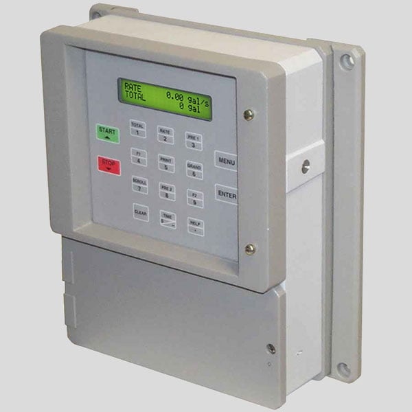
The alphanumeric display clearly displays measured and computed parameters. Direct access to measurements and display scrolling is available through a single key. The MS-716’s flexibility enables a high degree of adaptability inside the instrument package. Numerous hardware inputs and outputs can be “soft” allocated to accommodate a range of typical application requirements. While configuring the instrument, the user “soft chooses” the use of each input/output.
Through a menu setting, the isolated analog output may be set to track volume flow, corrected volume flow, mass flow, temperature, or density. This approach is capable of assigning the majority of hardware functionality.
The user can configure the standard RS-232 Serial Port for data logging, transaction printing, or remote meter reading through a modem connection. During system setup, a service or test mode is available to aid the user by monitoring inputs, exercising outputs, and publishing the system configuration.
Features:
- Class I Division II
- Vehicle Mount Enclosure; Rugged Aluminum Construction
- Provisions for Sealing
- Isolated Outputs Standard
- On Board Data Logging
- “EZ Setup” Guided Setup for First Time Users
- Rate/Total and Batching Functions
- Menu Selectable Hardware & Software Features
- Universal Viscosity Curve (UVC) and API Eq.
- Advanced Batching Features: Overrun Compensation, Autobatch Start, Print End of Batch, Slow Fill, 2 Stage Batching
- RS-232 Port Standard, RS-485 Optional Advanced Printing Capabilities Windows™ Setup Software
- DDE Server and HMI Software Available
- Enhanced Modem Features for Remote Metering
- IP65
Specifications
| Flow Meters and Computations | |
| Meter Types: All linear and square law meters supported | |
| including: Coriolis, vortex, turbine, magnetic, PD, target, | |
| orifice, venturi, v-cone and many others | |
| Linearization: Square root, 16 point table or UVC table | |
| Computations: Volume, Corrected Volume & Mass | |
| Fluid Computations: Temperature, Density, Viscosity and API 2540 for petroleum. | |
| Environmental | |
| Indoor Use | |
| Altitude up to 2000m | |
| Operating Temperature: | |
| (-20°C to 55°C optional) | |
| Storage Temperature: | |
| Maximum Relative Humidity: 80% for temperatures up to 31°C decreasing linearly to 50% RH at 40°C | |
| Mains supply voltage fluctuations not to exceed ±10% of the nominal voltage | |
| Transient overvoltage according to INSTALLATION CATEGORY II (see UL 3101-1 Annex J) | |
| POLLUTION DEGREE 2 in accordance with IEC 664 (see 3.7.3) | |
| Materials: UL, CSA, VDE approved UL Class 1 Division 2 (optional) | |
| Listing | UL/ULC Listed (File No. E192404), CE Compliant |
| Display | Display |
| Type: 2 lines of 20 characters | |
| Types: Backlit LCD or OLED | |
| Character Size: 0.2” nominal | |
| User programmable label descriptors and units of measure | |
| Keypad | |
| Keypad Type: Membrane Keypad with 16 keys | |
| Keypad Rating: Sealed to NEMA 4X / IP65 | |
| Enclosure | |
| Size: See Dimensions | |
| Seal: NEMA4X | |
| Materials: Aluminum | |
| Real Time Clock | |
| The MS-716 is equipped with a battery backed real time clock with display of time and date. | |
| Format: 12 or 24 hour time display | |
| Day, Month, Year date display | |
| Power Input | |
| The factory equipped power option is internally fused. An internal line to line filter capacitor and MOV are provided for added transient suppression. | |
| 110 VAC Power: 85 to 127 Vrms, 50/60 Hz | |
| 220 VAC Power: 170 to 276 Vrms, 50/60 Hz | |
| DC Power: | |
| 12 VDC (10 to 14 VDC) | |
| 24 VDC (14 to 28 VDC) | |
| Power Consumption: | |
| AC: 11.0 VA (11W) | |
| DC: 300 mA max. | |
| Flow Inputs | |
| Analog Input | |
| Accuracy: 0.01% FS at 20° C | |
| Ranges | |
| Voltage: 0-10 VDC, 0-5 VDC, 1-5 VDC | |
| Current: 4-20 mA, 0-20 mA | |
| Basic Measurement Resolution: 16 bit | |
| Update Rate: 4 updates/sec | |
| Automatic Fault detection: Signal over/under-range, Current Loop Broken | |
| Calibration: Software Calibration (no trimmers) and Auto-zero Continuously | |
| Extended calibration: | |
| Learns Zero and Full Scale of each range using special test mode. | |
| Fault Protection: | |
| Reverse Polarity: No ill effects | |
| Over-Voltage Limit: 50 VDC Over voltage protection | |
| Over-Current Protection: Internally current limited protected to 24VDC | |
| Pulse Inputs | |
| Number of Flow Inputs: one with or without quadrature | |
| Input Impedance: 10 KΩ nominal | |
| Pullup Resistance: 10 KΩ to 5 VDC (menu selectable) | |
| Pull Down Resistance: 10 KΩ to common | |
| Trigger Level: (menu selectable) | |
| High Level Input | |
| Logic On: 3 to 30 VDC | |
| Logic Off: 0 to 1 VDC | |
| Low Level Input (mag pickup) | |
| Sensitivity: | |
| 10 mV or 100 mV | |
| Minimum Count Speed: | |
| Menu Selectable: 40Hz, 3000Hz or 20 kHz | |
| Overvoltage Protection: 50 VDC | |
| Auxiliary / Compensation Input | |
| The auxiliary/compensation input is menu selectable for | |
| temperature, density or not used. This input is used for | |
| the compensated input when performing compensated | |
| flow calculations and using volumetric flowmeters. It | |
| can also be used as a general purpose input for display | |
| and alarming. | |
| Operation: Ratiometric | |
| Accuracy: 0.01% FS at 20° C | |
| Basic Measurement Resolution: 16 bit | |
| Update Rate: 1 update/sec minimum | |
| Automatic Fault detection: | |
| Signal Over-range/under-range | |
| Current Loop Broken | |
| RTD short | |
| RTD open | |
| Fault mode to user defined default settings | |
| Fault Protection: | |
| Reverse Polarity: No ill effects | |
| Over-Voltage Limit (Voltage Input): 50 VDC | |
| Available Input Ranges | |
| Voltage: 0-10 VDC, 0-5 VDC, 1-5 VDC | |
| Current: 4-20 mA, 0-20 mA | |
| Resistance: 100 Ohms DIN RTD | |
| 100 Ohm DIN RTD | |
| (DIN 43-760, BS 1904): | |
| Three Wire Lead Compensation | |
| Internal RTD linearization learns ice point resistance | |
| 1 mA Excitation current with reverse polarity protection | |
| Temperature Resolution: 0.01 C | |
| Control Inputs | |
| Switch Inputs are menu selectable for Start, Stop, Reset, | |
| Lock, Inhibit, Alarm Acknowledge, Print or Not Used. | |
| Control Input Specifications | |
| Input Scan Rate: 10 scans per second | |
| Logic 1: 4 - 30 VDC | |
| Logic 0: 0 - 0.8 VDC | |
| Input Impedance: 100 KΩ | |
| Control Activation: | |
| Positive Edge or Pos. Level based on product definition for switch usage. | |
| Excitation Voltage | |
| Menu Selectable: 5, 12 or 24 VDC @ 100 mA (fault protected) | |
| NOTE: DC powered units have limited excitation voltage | |
| Relay Outputs | |
| The relay outputs are menu assignable to (Individually | |
| for each relay) Low Rate Alarm, Hi Rate Alarm, Prewarn | |
| Alarm, Preset Alarm or General purpose warning | |
| (security), low temperature/high temperature. | |
| Number of relays: 2 (4 optional) | |
| Contact Style: Form C contacts | |
| Contact Ratings: 5 amp, 240 VAC or 30 VDC | |
| Serial Communication | |
| The serial port can be used for printing, datalogging, | |
| modem connection and communication with a computer. | |
| RS-232: | |
| Device ID: 01-99 | |
| Baud Rates: 300, 600, 1200, 2400, 4800, 9600, 19200 | |
| Parity: None, Odd, Even | |
| Handshaking: None, Software, Hardware | |
| Print Setup: Configurable print list and formatting. | |
| Print Out: Custom form length, print headers, print list. | |
| Print Initialization: Print on end of batch, key depression, interval, time of day or remote request. | |
| RS-485: (optional 2nd COM port) | |
| Device ID: 01-247 | |
| Baud Rates: 1200, 2400, 4800, 9600, 19200 | |
| Parity: None, Odd, Even | |
| Protocol: Modbus RTU (Half Duplex) | |
| Data Logging | |
| The data logger captures print list information to internal | |
| storage for approximately 1000 transactions. This | |
| information can be used for later uploading or printing. | |
| Storage format is selectable for Comma-Carriage Return | |
| or Printer formats. | |
| Isolated Analog Output | |
| The analog output is menu assignable to correspond to | |
| the Uncompensated Volume Rate, Corrected Volume | |
| Rate, Mass Rate, Temperature, Density, Volume Total, | |
| Corrected Volume Total or Mass Total. | |
| Type: Isolated Current Sourcing | |
| Available Ranges: 4-20 mA, 0-20 mA | |
| Resolution: 12 bit | |
| Accuracy: 0.05% FS at 20° C | |
| Update Rate: 1 update/sec minimum | |
| Temperature Drift: Less than 200 ppm/C | |
| Maximum Load: 1000 ohms (at nominal line voltage) | |
| Compliance Effect: Less than .05% Span | |
| 60 Hz rejection: 40 dB minimum | |
| Calibration: Operator assisted Learn Mode | |
| Averaging: User entry of damping constant to cause | |
| a smooth control action | |
| NOTE: DC powered units are not isolated | |
| Isolated Pulse output | |
| The isolated pulse output is menu assignable to | |
| Uncompensated Volume Total, Compensated Volume | |
| Total or Mass Total | |
| Pulse Output Form: Photomos Relay | |
| Maximum On Current: 25 mA | |
| Maximum Off Voltage: 30 VDC | |
| Saturation Voltage: 1.0 VDC | |
| Maximum Off Current: 0.1 mA | |
| Pulse Duration: 10 mSec or 100 mSec (user selectable) | |
| Pulse output buffer: 256 | |
| Fault Protection | |
| Reverse polarity: Shunt Diode |















What others are saying
There are no contributions yet.